

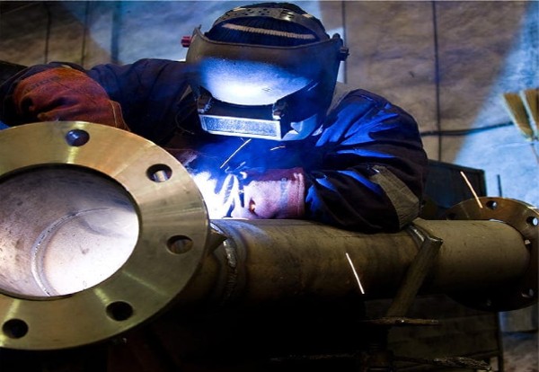
Non-Destructive Examination (NDE) is a crucial aspect of the manufacturing...
Read MoreFAQ
ASME Boiler & Pressure Vessel Code (BPVC) FAQ
Explore the most common ASME BPVC questions — from General FAQ, Design rules to Certification and Inspection requirements.
The ASME BPVC is an internationally recognized standard governing design, fabrication, inspection, testing, and certification of boilers and pressure vessels to ensure safety and quality.
Enforcement is carried out by jurisdictions, insurance companies, or Authorized Inspection Agencies that adopt ASME standards into their regulations.
ASME publishes a new edition every two years, typically in July of odd-numbered years, with interim Code Cases and Interpretations released as needed.
Certification demonstrates that a manufacturer’s quality system, design, and fabrication comply with ASME standards, allowing them to apply an official Code Symbol Stamp.
The correct Section depends on equipment type—Section I for power boilers, Section IV for heating boilers, Section VIII for pressure vessels, Section X for FRP vessels, and Section XII for transport tanks.
It depends on the jurisdiction. Most states require ASME-stamped vessels for commercial or industrial service, but small or private systems may be exempt.
The 'U' stamp applies to pressure vessels (Section VIII-1), 'S' to power boilers (Section I), and 'R'—issued by the National Board—covers repairs and alterations to pressure-retaining items.
ASME provides minimum standards for safety and design, while jurisdictions may impose additional registration, inspection, or operator requirements.
Yes, ASME Code-stamped equipment is recognized globally and often required for import, operation, or insurance compliance.
The BPVC can be purchased through ASME, Techstreet, or IHS Markit. Many organizations maintain digital subscriptions for their engineering teams.
Section VIII Division 1 covers the rules for construction of unfired pressure vessels that operate at pressures above 15 psig. It establishes requirements for design, materials, fabrication, inspection, testing, and certification.
| • Division 1 – Design-by-Rule | standard vessels up to about 3,000 psi. | ||||
| • Division 2 – Design-by-Analysis | higher-stress vessels up to 10,000 psi. | ||||
| • Division 3 – High-Pressure Vessels | over 10,000 psi with specialized design methods. | ||||
A Code Symbol Stamp is the physical mark (such as U, S, H, or R) applied to a nameplate that certifies the item meets all applicable ASME BPVC requirements verified by an Authorized Inspector.
ASME BPVC governs pressure-retaining equipment
It’s a document issued by ASME that allows a company to apply the appropriate Code Symbol Stamp. The certificate verifies that the company’s quality-control system meets all Code requirements.
Yes. A company may hold several Certificates of Authorization—such as “S,” “U,” and “PP”—as long as its quality-control program addresses each scope.
It indicates the item was designed and built in accordance with ASME rules but was not inspected or certified by an Authorized Inspector
Interpretations are formal replies issued by ASME committees clarifying specific Code requirements. They carry the same authority as the written Code.
At least as long as stated in their quality-control manual, typically the life of the product or per jurisdictional retention rules—often 5–10 years.
It’s a unique code assigned by ASME that identifies the manufacturer on the nameplate. It links the stamped vessel to the Certificate of Authorization holder.
It means all work was performed per the applicable ASME section, under a certified QC system, and inspected by an Authorized Inspector before stamping.
Any vessel designed for an internal or external pressure greater than 15 psig falls under ASME Section VIII Division 1 unless specifically exempted by the Code or local jurisdiction.
A boiler, covered by Sections I or IV, generates or heats fluid
A Code Case provides alternative rules or permits new materials and methods not yet in the published Code. It must be formally adopted by the manufacturer and the Authorized Inspector.
It’s a unique code assigned by ASME that identifies the manufacturer on the nameplate. It links the stamped vessel to the Certificate of Authorization holder.
It means all work was performed per the applicable ASME section, under a certified QC system, and inspected by an Authorized Inspector before stamping.
The jurisdiction may require an engineering assessment, repairs under NBIC guidelines, or in severe cases, removal from service. Traceable records and transparency help determine the resolution.
Code Cases can expire or be withdrawn. When that happens, the rules within are no longer valid unless incorporated into the next BPVC edition.
Only materials listed in ASME Section II, Part D, or those approved through a Code Case are allowed. Each material has defined allowable stress values.
Corrosion allowance adds extra wall thickness to account for expected material loss in service, typically 1⁄16 to 1⁄8 inch for carbon steel vessels.
Design pressure is the maximum safe pressure at design temperature, usually 10–15% above operating pressure for a safety margin.
It is the highest metal temperature expected during operation and determines allowable material stresses from Section II, Part D.
Reinforcement replaces metal lost at openings with pads or thicker material per UG-37 to UG-45 to maintain vessel strength.
They are listed in Section II, Part D and based on tensile, yield, or creep limits divided by appropriate safety factors.
Joint efficiency accounts for weld quality and extent of NDE
Yes, especially under Section VIII Division 2 (Design-by-Analysis) for complex geometries where standard formulas don’t apply.
Other loads include wind, seismic, nozzle, thermal, and weight loads—all must be included in design per UG-22.
Minimum Design Metal Temperature defines the lowest temperature the vessel can safely operate without brittle fracture, governed by UCS-66.
Maximum Allowable Working Pressure (MAWP) is the highest pressure permitted at the top of the vessel in its operating position for the designated temperature. It is the lowest calculated value among all components.
UG-28 through UG-30 of Section VIII Division 1 provide charts and formulas for shells and heads under external pressure to prevent buckling.
UG-28 through UG-30 of Section VIII Division 1 provide charts and formulas for shells and heads under external pressure to prevent buckling.
Designers may add additional corrosion allowance or specify protective coatings and insulation systems that minimize moisture intrusion per API Recommended Practice 583.
Drawings must show design pressure and temperature, materials, joint details, nozzle sizes, weld categories, and Code references so the AI can verify Code compliance.
Corrosion allowance is added thickness to permit uniform metal loss
For most ferrous materials, allowable stress equals the lesser of one-third of tensile strength or two-thirds of yield strength, adjusted for temperature.
Expansion joints, flexible piping, or sliding supports are used so that temperature-induced movement doesn’t overload shell or nozzle welds.
UG-27 gives formulas for calculating minimum thickness of cylindrical and spherical shells under internal pressure—one of the most frequently applied paragraphs.
Efficiency is reduced based on weld category and the percentage of examination
Incorrect material selection, overlooked load cases (like wind or thermal stress), or using default joint efficiencies without verifying NDE coverage.
Only if supported by a Code Case or included in Division 2’s Design-by-Analysis rules. Otherwise, designs must follow the formulas provided in Section VIII.
Shells are calculated based on internal pressure and diameter.
Maximum Allowable Working Pressure (MAWP) is the highest pressure permitted at the top of the vessel in its operating position for the designated temperature. It is the lowest calculated value among all components.
UG-28 through UG-30 of Section VIII Division 1 provide charts and formulas for shells and heads under external pressure to prevent buckling.
Only if supported by a Code Case or included in Division 2’s Design-by-Analysis rules. Otherwise, designs must follow the formulas provided in Section VIII.
Shells are calculated based on internal pressure and diameter
For most ferrous materials, allowable stress equals the lesser of one-third of tensile strength or two-thirds of yield strength, adjusted for temperature.
UG-27 gives formulas for calculating minimum thickness of cylindrical and spherical shells under internal pressure—one of the most frequently applied paragraphs.
Minimum Design Metal Temperature defines the lowest temperature the vessel can safely operate without brittle fracture, governed by UCS-66.
A WPS defines how a weld is made, listing base material, filler, preheat, PWHT, and process variables. It’s supported by a Procedure Qualification Record (PQR).
PWHT relieves residual stresses and restores toughness. Requirements depend on material, thickness, and service condition per UCS-56.
Welders are qualified under Section IX by making a test coupon using a WPS, which is then tested for compliance with Code acceptance criteria.
Essential variables affect weld properties and require requalification if changed
A Procedure Qualification Record documents test results that prove a WPS produces sound welds with acceptable mechanical properties.
Radiography, ultrasonic, magnetic-particle, and liquid-penetrant exams verify weld soundness depending on joint category and Code requirements.
Thin materials or certain low-alloy steels may be exempt per Code tables if they meet toughness and service criteria.
Yes, as long as they follow the manufacturer’s Quality Control system and are approved by the Authorized Inspector before stamping.
A welder’s qualification remains valid if they weld with the qualified process every six months or as per company QC records.
MTRs, WPS/PQR/WPQR, NDE reports, and AI sign-offs are mandatory for Code data package completion.
A hold point is a designated step in manufacturing where work pauses until the Authorized Inspector verifies compliance and authorizes continuation.
Filler metals must conform to Section II Part C specifications, be stored per manufacturer recommendations, and have batch traceability documented in QC records.
Back-purging uses inert gas on the root side of stainless or high-alloy welds to prevent oxidation
Section VIII identifies joint categories A–D based on location and stress significance
Tack welds hold components temporarily for alignment
Each weld repair must be logged with defect location, cause, repair method, NDE results, and AI approval in the fabrication traveler or repair report.
Temporary lugs or clips must be removed and the area examined for cracks or undercut before final hydrotesting.
Preheating reduces thermal gradients and hydrogen cracking risk by raising the base-metal temperature before welding
Each welder must be traceable to the welds they perform, usually through unique stamps or symbols recorded in the manufacturer’s weld map.
In ASME Section VIII, Category A refers to longitudinal welds in cylindrical shells and the inside welds of heads — the most critical joints for pressure integrity.
Yes, but only within the qualified diameter and thickness range per Section IX. Pipe-to-pipe and plate-to-plate tests qualify differently for position and geometry.
Yes, but the affected area must be re-examined using the original NDE method and re-tested if the pressure boundary was involved.
Welding between different base metals (e.g., carbon steel to stainless steel) requires careful filler metal selection, preheat, and postweld control to prevent cracking or galvanic corrosion.
A WPS defines how a weld is made, listing base material, filler, preheat, PWHT, and process variables. It’s supported by a Procedure Qualification Record (PQR).
PWHT relieves residual stresses and restores toughness. Requirements depend on material, thickness, and service condition per UCS-56.
Welders are qualified under Section IX by making a test coupon using a WPS, which is then tested for compliance with Code acceptance criteria.
Essential variables affect weld properties and require requalification if changed
Welding between different base metals (e.g., carbon steel to stainless steel) requires careful filler metal selection, preheat, and postweld control to prevent cracking or galvanic corrosion.
A Procedure Qualification Record documents test results that prove a WPS produces sound welds with acceptable mechanical properties.
Temporary lugs or clips must be removed and the area examined for cracks or undercut before final hydrotesting.
Preheating reduces thermal gradients and hydrogen cracking risk by raising the base-metal temperature before welding
Each welder must be traceable to the welds they perform, usually through unique stamps or symbols recorded in the manufacturer’s weld map.
Proper heat input prevents cracking and distortion. Heat must be controlled within WPS limits to maintain material properties and joint integrity.
The Code specifies radiography, ultrasonic, magnetic-particle, liquid-penetrant, and visual inspection based on joint type and service pressure.
A hydrotest verifies vessel strength by applying about 1.3 times design pressure with water to confirm leak-tightness.
Only when hydrotesting is impractical, such as for sensitive linings. Pneumatic tests require strict safety precautions and lower test pressures.
A Manufacturer’s Data Report records design, materials, inspections, and tests. It must be signed by the manufacturer and Authorized Inspector.
The AI verifies Code compliance, witnesses required tests, reviews documentation, and signs the Data Report prior to stamping.
Certificates of Authorization last three years and require a successful Joint Review for renewal.
Manufacturers submit the signed Data Report to the National Board for permanent registration and traceability.
Safety valves are capacity-certified, set to open at or below MAWP, and sealed after testing per UG-125–UG-136.
Typical issues include missing documentation, unqualified welders, incorrect material traceability, or incomplete NDE reports.
All fabrication, inspection, and test documents must be kept per the QC Manual for audits or renewals.
The AIA assigns the Authorized Inspector; ASME’s Team Leader coordinates the review, ensuring the manufacturer’s QC system meets Code expectations before certificates are renewed.
MT uses magnetic fields and ferrous particles to detect surface or near-surface discontinuities in ferromagnetic materials. It’s effective for weld toes and attachment welds.
Incomplete weld fusion, overlooked porosity, or temporary test equipment leaks. Repairs must follow an approved procedure and be re-examined before acceptance.
The AI reviews all Data Reports, NDE summaries, calibration records, and material certifications to confirm completeness prior to stamping.
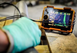
UT uses high-frequency sound waves to detect internal flaws and measure wall thickness. It’s an accepted alternative to radiography for many joints.
PT applies dye to the surface, allowing cracks or porosity to show under ultraviolet or visible light after developer application; it’s used on non-ferrous or finished surfaces.
It defines how the organization ensures Code compliance through procedures for material control, welding, inspection, and record retention. The AI audits against it.
After applying for renewal, the manufacturer coordinates dates through CA Connect. ASME and the AIA jointly review the facility’s quality system and a demonstration item.
The team issues findings that must be corrected within a specified time before ASME will renew or issue the Certificate of Authorization.
It’s a documentation form used when a component (like a heat exchanger tube bundle) is built by a sub-supplier. It is later attached to the main vessel’s full data report.
No. Stamping must occur only after all required inspections and the final hydrostatic test are completed and accepted by the AI.
A Joint Review is for original certification or renewal. A Field Audit verifies continued compliance between reviews, especially if issues were found previously.
Yes, if the subcontractor is qualified, their procedures are approved, and the results are reviewed and accepted under the manufacturer’s QC system.
Radiographic testing uses X-rays or gamma rays to detect internal flaws in welds. It’s required for certain joint categories in Section VIII to establish joint efficiency E.
UT uses high-frequency sound waves to detect internal flaws and measure wall thickness. It’s an accepted alternative to radiography for many joints.
MT uses magnetic fields and ferrous particles to detect surface or near-surface discontinuities in ferromagnetic materials. It’s effective for weld toes and attachment welds.
PT applies dye to the surface, allowing cracks or porosity to show under ultraviolet or visible light after developer application; it’s used on non-ferrous or finished surfaces.
The defect must be repaired per an approved procedure, re-examined by the same NDE method, and accepted by the AI before fabrication continues.
A Joint Review is for original certification or renewal. A Field Audit verifies continued compliance between reviews, especially if issues were found previously.
Yes, if the subcontractor is qualified, their procedures are approved, and the results are reviewed and accepted under the manufacturer’s QC system.
No. Stamping must occur only after all required inspections and the final hydrostatic test are completed and accepted by the AI.
It’s a documentation form used when a component (like a heat exchanger tube bundle) is built by a sub-supplier. It is later attached to the main vessel’s full data report.
The AI cannot sign the Data Report until the missing documentation is provided, reviewed, and verified. All inspection records must be complete before stamping.
Repairs and alterations after construction follow NBIC rules and are inspected by a National Board-Commissioned Inspector under an R-stamp program.
Only with a Code Case or approval verifying equivalent strength and documentation.
The National Board Inspection Code governs repair, alteration, and in-service inspection of pressure-retaining items after installation.
A repair restores original design conditions, while an alteration changes design parameters such as MAWP or material type.
Re-rating requires engineering analysis under the original Code of construction and AI acceptance recorded on Form R-2.
It’s periodic examination of operating vessels to detect corrosion, cracking, or mechanical damage, ensuring continued safety.
Yes, if original documentation exists and the vessel passes inspection confirming compliance with Code limits.
Forms R-1/R-2, updated drawings, NDE reports, and AI sign-off are mandatory for registration.
National Board-Commissioned Inspectors from Authorized Inspection Agencies perform and verify NBIC compliance.
They must stop Code repair work and undergo a Joint Review to requalify their Quality System.
Form R-3 documents the replacement, addition, or relocation of parts not directly affecting the pressure boundary, such as supports or nameplates, under NBIC guidelines.
A company authorized by a jurisdiction or the National Board to inspect and repair its own equipment under a written quality system meeting NBIC Part 2.
Frequency is defined by jurisdiction or company program—typically every 1–5 years for pressure vessels, depending on service severity and corrosion rate.
The repair organization must keep the R-forms, revised drawings, NDE reports, and AI authorization for the life of the equipment.
Relief valves must be tested or certified at intervals defined by jurisdiction or NBIC Part 4 to verify proper set pressure and reseating performance.
Engineering evaluation, inspection, and pressure testing can establish a new MAWP, followed by registration under NBIC guidelines if accepted by the jurisdiction.
An FFS evaluation analyzes corrosion, cracks, or deformation to determine if a vessel can continue safe operation without immediate repair.
Whenever a vessel is moved between states or provinces, ownership changes, or a major alteration modifies its design conditions.
Whenever a vessel is moved between states or provinces, ownership changes, or a major alteration modifies its design conditions.
The AI reviews the repair plan, witnesses any pressure tests, and signs the R-Form verifying that the work conforms to NBIC Part 3 requirements.
It allows organizations to perform repairs and alterations to ASME-stamped items using NBIC procedures, provided they pass a joint audit by the National Board and their AIA.
Localized UT examines specific areas for flaws, often after repairs. Full-coverage UT scans the entire joint length as an alternative to radiography when permitted.
The AI must review design changes, verify Code compliance, and witness testing or inspection necessary to validate the new condition of the item.
A rerate changes the allowable working pressure or temperature without physical modification; an alteration physically changes the vessel and requires new calculations and documentation.
Repairs and alterations after construction follow NBIC rules and are inspected by a National Board-Commissioned Inspector under an R-stamp program.
Form R-1 for repairs or R-2 for alterations, signed by the repair organization and the Authorized Inspector, becomes part of the vessel’s permanent record.
Yes, provided the original nameplate and Data Report exist and the vessel passes inspection confirming it meets the original Code of construction.
An FFS evaluation analyzes corrosion, cracks, or deformation to determine if a vessel can continue safe operation without immediate repair.
NBIC permits 'hot work' or in-service welding under strict controls, with jurisdiction approval, an R-stamp, and full NDE to verify integrity.
Part 2 covers in-service inspection requirements — including condition assessment, fitness-for-service evaluations, and jurisdictional reporting guidelines.
Yes, but the new jurisdiction may require review or re-registration. The original R-Form and inspection documents must accompany the vessel.
Many jurisdictions allow exceptions for antique or historical boilers, provided they operate under strict limitations and safety review per NBIC Appendix G.
Looking for ASME Joint Review FAQ?
Pre-Joint Review Checklist
Go into your Joint Review with confidence. Use our Pre-Joint...
Read More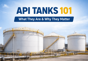
API Tanks 101: What Are API Storage Tanks
An API storage tank is a large, welded storage tank...
Read More