

Heat Exchanger
Heat exchangers are used to transfer heat from one medium to another. These media may be a gas, liquid, or a combination of both. The media may be separated by a solid wall to prevent mixing or may be in direct contact. Heat exchangers are required to provide heating and/or cooling to meet a process requirement. Typically, any direct heat input to the system comes from a furnace or steam. Therefore, any inefficiency in the heat transfer at exchangers will require a higher amount of duty from the furnace or steam.
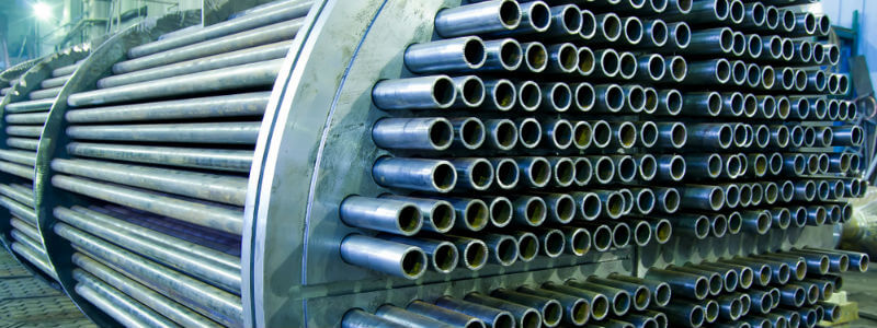
Pictured above: Inside of a Heat Exchanger
Heat exchangers can also improve a system’s energy efficiency by transferring heat from systems where it is not needed to other systems where it can be usefully used. In general, heat exchangers are used to exchange heat between two or more process streams or between process stream(s) and a utility stream, which can be either hot or cold utilities.
The selection between using a direct process-to-process heat exchanger versus using utilities to transfer heat depends on the temperature and pressure required by the process stream and whether there is an available process stream to provide that duty given the temperature approach required. When there is no process stream available, a utility stream is required to provide the heating or cooling duty required.
Heat exchanger flow configurations
Heat exchangers have three primary flow configurations:
- Parallel flow: The two fluids enter at the same end of the heat exchanger and flow in the same direction, parallel to one another. In this design, the temperature differences are large at the inlet, but the fluid temperatures will approach a similar value at the outlets.
- Counterflow: The two fluids enter at opposite ends of the heat exchanger and flow counter to one another. In this design, the temperature differences are less but are more constant over the length of the exchanger. It is possible that the fluid being heated may leave the exchanger at a higher temperature than the exit temperature of the heating fluid. This is the most efficient design because of the higher temperature differential over the length of the exchanger.
- Crossflow: The two fluids flow perpendicular to one another.
There can be more than one method of heat transfer in a heat exchanger. Heat transfer will occur using one or more modes of transfer, conduction, convection, or radiation.
Several examples of heat exchanger applications follow:
- Waste heat recovery in the exhaust of an electricity-generating gas turbine. Heat can be transferred via a heat exchanger to heat a process stream directly or indirectly via an intermediate heating medium such as water or hot oil. This is the basis for cogeneration. For more information refer to the Combined Heat and Power Info Sheet.
- Utilizing process heat recovery, which can be optimized via the pinch technique for more complex systems (refer to the Pinch Analysis Info Sheet). A specific example of this would be developing a heat exchanger network to recover the heat from a distillation train to preheat the incoming feed and preheating of crude for water/oil separation.
- Using a utility, for example, water, steam, hot oil, and molten salt, to provide heat duty to a process stream.
- Using a utility, for example, air, cooling water, and refrigerant, to provide a cooling duty to a process stream.
- Selection of the type of hot utility mainly depends on the inlet and outlet target temperatures required by the process stream. Other factors for consideration include the specific heat capacity, cost of the utility, and process safety.
Heat exchangers can be classified according to their construction as stated below:
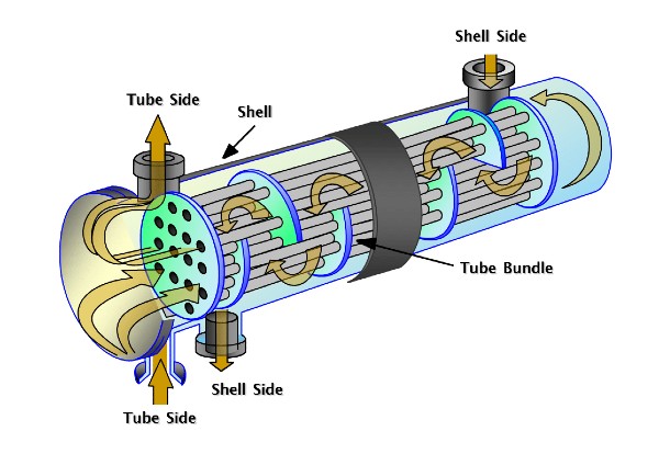
Pictured above: Basics-of-Shell-Tube-Heat-Exchangers
Shell and tube heat exchangers – Shell and tube exchangers are the most used heat exchangers in process plants today. The reasons for this are that shell and tube heat exchangers can operate on a wide range of operating temperature and pressure and It has well-established procedures and availability of codes and standards for design and fabrication.
Shell and tube heat exchangers can further be divided into 4 major categories.
1. Kettle-type heat exchanger – The kettle-type exchanger also uses the same working method as shell and tube heat exchangers, but the importance of this type is that it is used for partially vaporizing the shell fluid. It is used as a kettle reboiler in the process industry and flooded chillers in the refrigeration industry. The most distinguished feature of a kettle-type exchanger is its shape. It consists of a horizontal U-tube or floating head bundle placed in an oversized shell. The tube bundle is free to move and removable. The large empty space above the tube bundle acts as a vapor-disengaging space. The liquid to be vaporized enters at the bottom, near the tube sheet, and covers the tube bundle; the vapor occupies the upper space in the shell, and the dry vapor exists from the top nozzles, while a weir helps to maintain the liquid level over the tube bundle. The bottom nozzle in this space is used to drain the Excel liquid.
2. U tube exchanger – Here the tubes can expand and contract freely but there is only one stationary tube sheet required. For inspection of tubes in this type of exchanger, the tube bundle must be pulled out. U-tube exchangers are used when the fluid involved is cold and the tubes are less likely to expand or foul inside. Below is an animation for u tube exchanger.
3. Fixed head shell and tube heat exchanger – This is the simplest and most popular type of exchanger. These types of exchangers are constructed with the tube sheet integral to the shell. It uses straight tubes secured at both ends into tube sheets, which are firmly welded to the shell. These have no provision for tube expansion. The temperature limit of heat exchangers is 65 deg. The end covers are removable, so the inside of the tubes can be cleaned by rodding or similar tools, but the inside surface of the shell cannot be cleaned, and it relies upon the shell side fluid to clean it. Below is an animation for u tube exchanger.
4. Kettle-type heat exchanger – The kettle-type exchanger also uses the same working method as shell and tube heat exchangers, but the importance of this type is that it is used for partially vaporizing the shell fluid. It is used as a kettle reboiler in the process industry and flooded chillers in the refrigeration industry. The most distinguished feature of a kettle-type exchanger is its shape. It consists of a horizontal U-tube or floating head bundle placed in an oversized shell. The tube bundle is free to move and removable. The large empty space above the tube bundle acts as a vapor-disengaging space. The liquid to be vaporized enters at the bottom, near the tube sheet, and covers the tube bundle; the vapor occupies the upper space in the shell, and the dry vapor exists from the top nozzles, while a weir helps to maintain the liquid level over the tube bundle. The bottom nozzle in this space is used to drain the Excel liquid.
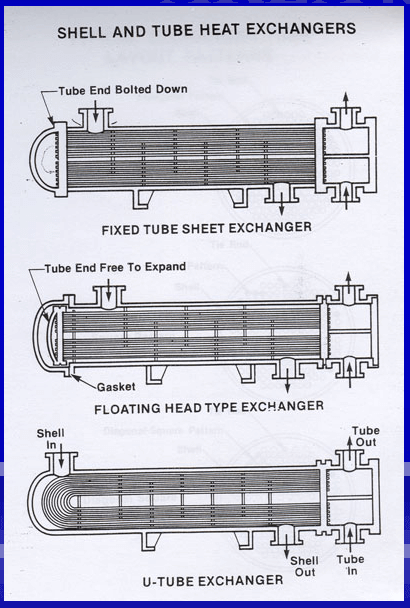
Pictured above: Shell and tube heat exchangers
Other types of Heat Exchangers
Other types of Heat Exchangers.
Other types of heat exchangers for specialized services include plate- type-heat exchangers, spiral heat exchangers, double type heat exchangers, and air cooled heat exchangers.
Plate-type heat exchangers
This type of exchanger is generally used for low pressure & low-temperature application. These usually consist of end covers, carrying bars, inlet/outlet nozzles, plates, and gaskets.
The carrying bar carries two end plates and a no of thin plates with gaskets between them. These plates have flow patterns carved out on them on which the fluid flows. The plates are arranged alternatively so that hot fluid flows in 1, 3, and 5 numbered plates while cold fluid flows in 2, 4 & 6 numbered plates. This arrangement lets the hot and cold fluid exchange heat while not mixing. The plate-type heat exchanger requires less installation and maintenance space than the shell and tube type of equivalent surface. A working animation is provided below for the plate-type heat exchanger.
Spiral heat exchangers
Spiral heat exchangers are generally used in chemical plants and are of circular construction. There are two plate strips wrapped to form a concentric spiral passage. They are arranged such that they form two concentric flow channels. The hot fluid flows in one channel and just next to it the cold fluid. This side-by-side flow is the basis for heat exchange between two fluids without mixing. Like the plate exchanger, the spiral exchanger is compact and requires less installation and maintenance space.
Double Pipe Heat Exchangers
Double pipe heat exchangers are used when one liquid has a greater resistance to heat flow than another or when the surface area is small. In such cases the addition of fins to the inner pipe increases the surface area available for heat transfer and in terms increases t efficiency of heat transfer. The double-pipe heat exchanger consists of an outer pipe and an inner pipe. Both outer and inner pipes have a return bend at one end. The inner pipe is fitted with fins while the outer pipe acts as a shell. Shell nozzles are mounted vertically from the outer pipe and the tube nozzles are directly welded to the inner pipe ends.
Air-Cooled Heat Exchanger
Air-cooled heat exchanger performs their cooling function by flowing large quantity of cooled air around a bank of finned tubes with the help of large fans. The combination of the Finned tube and the air-circulating FAN has made FIN-FAN cooler a common term used for air coolers.